Research
SAGEST Predictive Simulation Center · CFD & Propulsion Laboratory, UVA
2025-2026
SAGEST (Stochastic Simulations of Ablative Geometries with Error-Learning in Space and Time) is a DOE/NNSA PSAAP IV predictive simulation center led from the University of Virginia, with hypersonic flight as its test case. I worked in Dr. Xinfeng Gao's CFD & Propulsion Laboratory on the meshing side of that problem.
The target is a Maneuverable Reentry Vehicle (MaRV) at 40 km and , simulated in Chord, a fourth-order explicit finite-volume solver. Chord only accepts fully structured, pure-hexahedral multiblock meshes, and the vehicle's split flaps meet the cone in point-terminated corners that no hexahedral topology can fill.
2025-2026
Undergraduate Researcher · CFD & Propulsion Laboratory
- Built fully structured, pure-hexahedral multiblock meshes of a Mach 12.6 biconic reentry vehicle in Fidelity Pointwise for a fourth-order finite-volume solver: 1:1 conformal faces, 8n edge sizing, no degenerate edges.
- Removed a degenerate flap-hinge topology with a 0.01 in CAD trim, and bounded its cost at a 0.44% change in flap planform area.
- Reached the M∞ = 12.6 design condition in ANSYS Fluent by sequential Mach ramping (density-based, Roe FDS / AUSM, Spalart–Allmaras).
- Ran a ~78 M-cell refinement study showing that block-aligned field discontinuities survive refinement, so resolution alone is not their cause.
- Built a ~1 M-cell prism–tetrahedral comparison mesh with y⁺ ≈ 1 inflation layers to isolate the effect of the geometry approximation.
- Presented weekly to the lab in LaTeX/Beamer; co-authored the project's research poster.
- Freestream
- Altitude
- 40 km
- Conditions
- 277.52 Pa · 251.05 K
- Geometry
- 10.5° / 7° bicone, split flap
- Mesher
- Fidelity Pointwise
- Solvers
- Chord (target) · ANSYS Fluent
Interactive Vehicle Model
Interactive Structured Mesh
- Hex cells
- 119,296
- Nodes
- 131,490
- Tets / prisms / pyramids
- 0
- Wall faces
- 8,448
- Mean wall skewness
- 0.099
- All faces
- 370,048
Coarse mesh iteration 4 (August 2026), read straight from the Fluent case file Pointwise exported. Skewness here is the 2D equiangle skewness of each quad face, , computed for this page.
| Face set | Mean | 95th pct. | Max | > 0.85 |
|---|---|---|---|---|
| Wall surface | 0.099 | 0.468 | 0.9459 | 36 |
| All mesh faces | 0.098 | 0.438 | 0.9996 | 1,629 |
Most faces above 0.85 sit in the slice and flap region (x ≈ 25–32 in): at the slice leading edge and where the triangular wedge faces are split into quads.
June 2026
Structured Benchmark in ANSYS
The first structured mesh was built top-down in ANSYS: slice the domain into blocks, then sweep each one. A conical O-grid wrap at the nose, adapted from labmate Gabe Damiani's conic meshing approach, reduced skew in the front cells, and manual edge biasing carried resolution across the 10.5° to 7° cone junction. An earlier, coarser version ran and produced the right physics: an attached oblique shock, a hot shock layer, and a Mach 12.5 freestream, matching earlier tetrahedral results.
The workflow hit a wall the solver could not fix. The many geometry operations left tiny gaps between blocks, so interior block faces imported as one-sided walls that physically blocked the flow. Zone-type reassignment, interior naming, interface pairing, and SpaceClaim gap repair all failed, which moved the work to a dedicated structured mesher.
July 2026
Pointwise: Domain and Blocking
In Pointwise the mesh is built bottom-up from the surface. The outer boundary follows the shock envelope instead of a rectangular box, so cells are spent where the gradients are. Chord's 8n edge rule sets the coarsest legal block at 9 nodes (8 cells) per edge, and every subdivision propagates through the whole index space up- and downstream. That propagation constraint drove every decision after it.
| First full-mesh iteration | Value | Note |
|---|---|---|
| Total cells | 247,296 | deliberately coarse |
| Blocks | 64 | |
| Jacobian | positive throughout: valid mapping | |
| Min / max included angle | 21.1° / 173.6° | ideal 90°; localized at the flap decomposition |
July 2026
The Hinge Singularity
Where the two flap panels meet the shoulder, the geometry ends in a point. Any block that fills that corner needs a collapsed edge, so its Jacobian goes to zero, and Chord requires everywhere. With two flaps, the far-field extrusion inherits both pinch points. The fix had to be geometric: trim in off each outboard flap edge in SolidWorks, which turns the point into a short, finite, meshable edge.
| Surface | ΔA (in²) |
|---|---|
| Flap planform (2.29 → 2.28 in, ×2) | −0.066 |
| Shoulders (2.77 × δ, ×2) | +0.055 |
| Exposed base (0.53 × δ, ×2) | +0.011 |
| Net | 0.000 |
Every square inch removed from the flaps reappears on the shoulders and base, and the wedge angle is unchanged. High- flap surface is traded for near-zero- shoulder and base, so the force change is bounded by 0.44%. The price is a thin sliver band along the trimmed edge, a large transverse spacing jump the blocking has to route around.
Quick tetrahedral runs under the 1.048 M-cell student license cap, used to test the trim qualitatively. Neither converged at ; the trimmed geometry behaved marginally better. The two runs differ in flux scheme, so they carry no quantitative weight.
July 2026
Pure-Hex Volume Blocking
With the hinge resolved, the surface mesh and the full volume blocking went through: every face quadrilateral, every edge finite, block boundaries following the cone junction, slice, and flap edges into the volume. The nose moved from an O-H grid to a simple extrusion, which meant fewer awkward subdivisions at the cost of skew in the nose region.
August 2026
Mach Ramping to the Design Condition
Cold-started RANS converged cleanly at and stalled above it. Warm-starting each Mach number from the last converged field got the solution to the design condition: every step recovered, with no divergence and no scheme intervention.
| Ramp | Setting |
|---|---|
| Schedule | ~5,000 iterations per condition, no re-initialization between steps |
| Flux | Roe FDS throughout; AUSM for the final ~5,000 iterations |
| Model | Density-based, ideal gas, Sutherland viscosity, Spalart–Allmaras, adiabatic no-slip walls |
| Residuals | Each step spikes 2–3 orders, then relaxes; floor rises from 1e-3–1e-4 to 1e-1–1e-2 at M 12.6 |
A rising floor with a flat turbulence residual pointed at the mesh, not the model. Rebuilding the nose with an expanded hemisphere wrap pushed skew radially outward from the stagnation region and removed the radial artifacts at the tip; a seam remained at the nose-to-cone transition.
August 2026
Refinement Study: ~78 M Cells
The structured solutions showed sharp discontinuities aligned with interior block faces at three sites: the nose-to-cone junction, the flat-slice transition, and the base corner. The test was to hold geometry, topology, and solver settings fixed and change only the cell count. If the features were discretization error, they would fade under refinement.
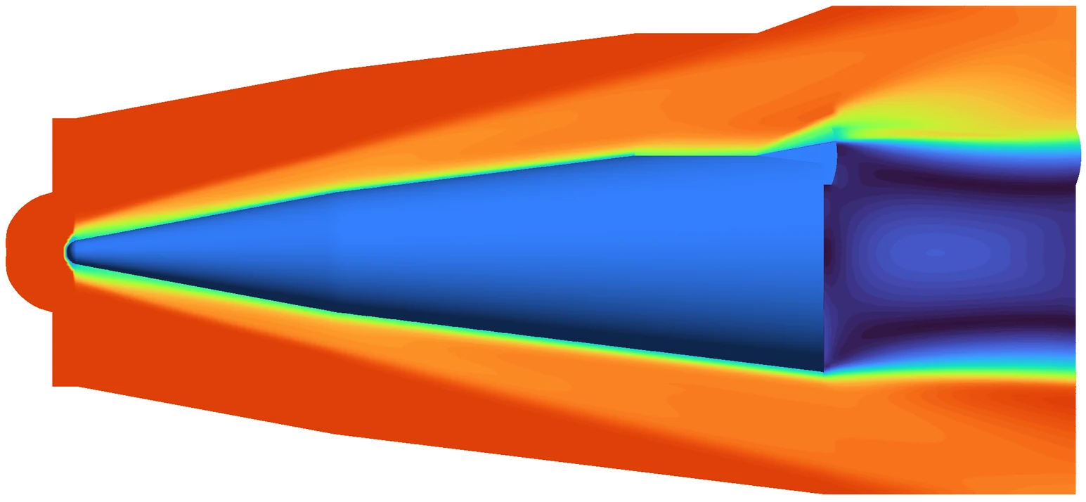
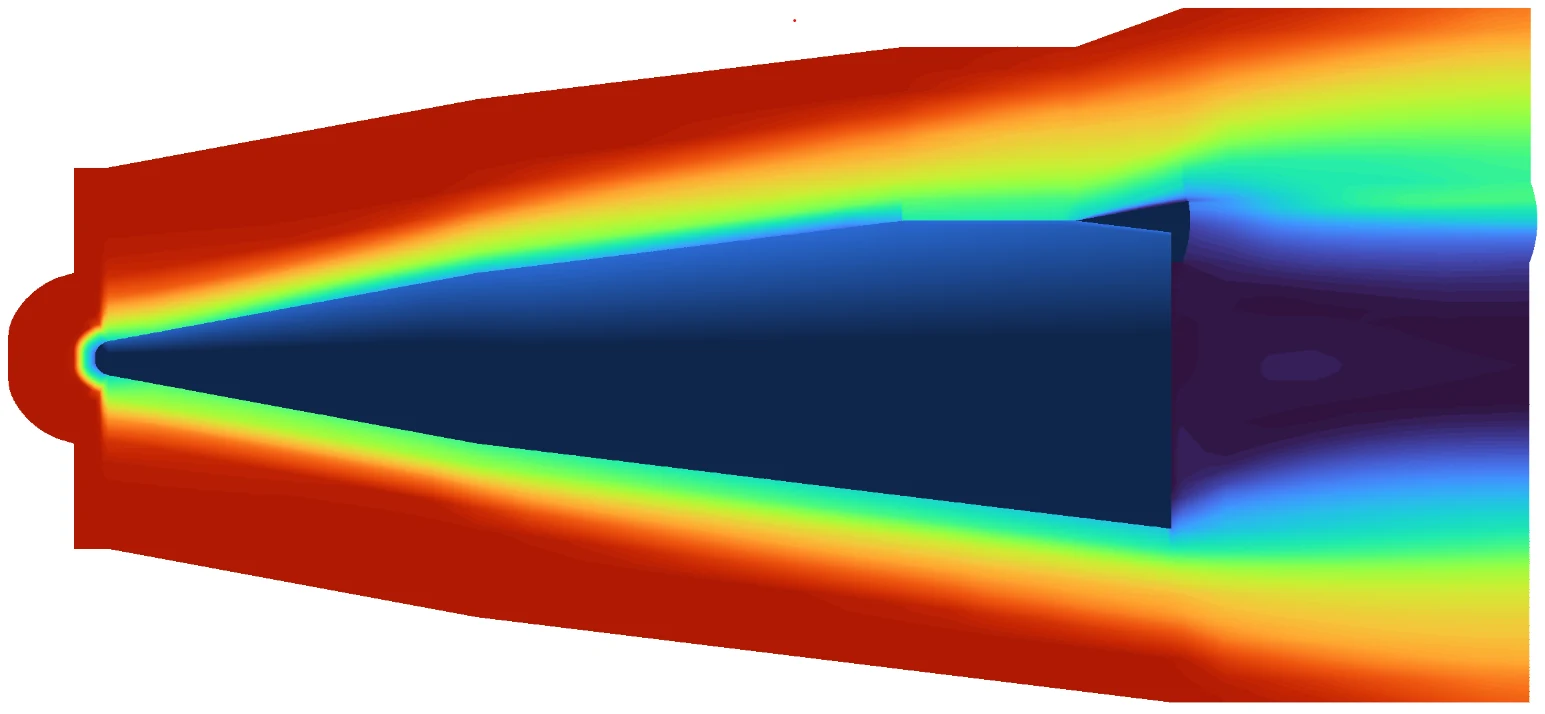
Drag the handle (or use ← →) to compare.


Mach number on the xy centerplane. The refined run reached M 6 in the available wall time, so the color scales differ (left: coarse, right: refined) and shock standoff changes with Mach. The comparison is structural: where the seams are, and whether they move.
| Region | Observation | Most consistent with |
|---|---|---|
| (a) Nose | Scalloped bow shock, amplitude ~1 cell; persists at shorter wavelength | Grid-induced: shock oblique to cell faces |
| (b) Flat slice | Mesh-aligned seam bounding the near-wall region | Mixed: physical expansion fan plus the high-aspect-ratio band from the trim |
| (c) Base corner | Vertical seam above the corner; isolated low-value cells | Grid-induced, plus possible non-convergence in the wake |
Refinement bought a thinner shock layer, a boundary layer distinct from the shock, and a resolved base recirculation that the coarse mesh missed. None of the three seams disappeared, so resolution alone is not the cause: they are tied to the block topology, the physics, or both. A tetrahedral run of the untrimmed geometry (unconverged, used for structure only) shows the same global flow with no block-aligned seams, because it has no block faces.
Research Poster
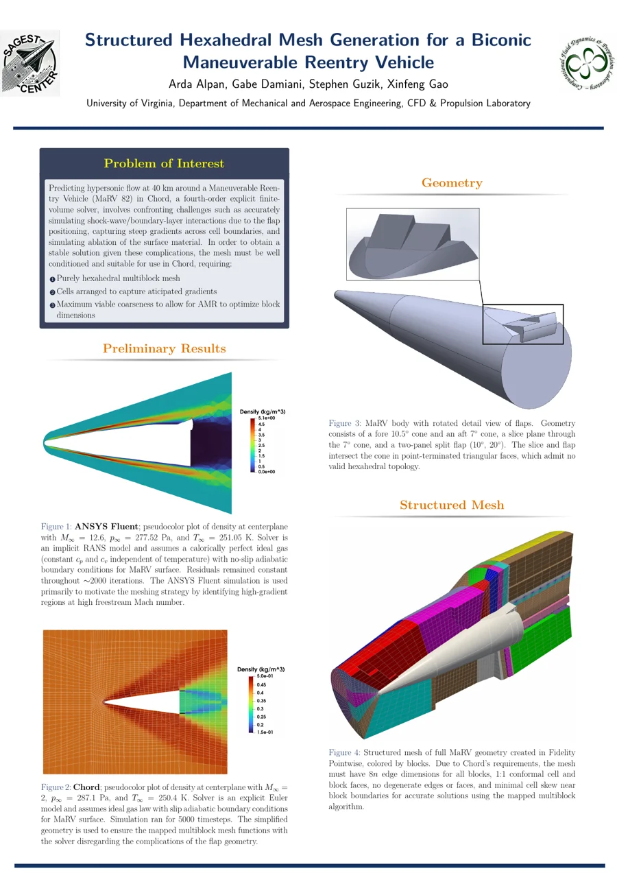
Structured Hexahedral Mesh Generation for a Biconic Maneuverable Reentry Vehicle
Arda Alpan, Gabe Damiani, Stephen Guzik, Xinfeng Gao · UVA CFD & Propulsion Laboratory
Open the poster (PDF)